Він пишу наступне
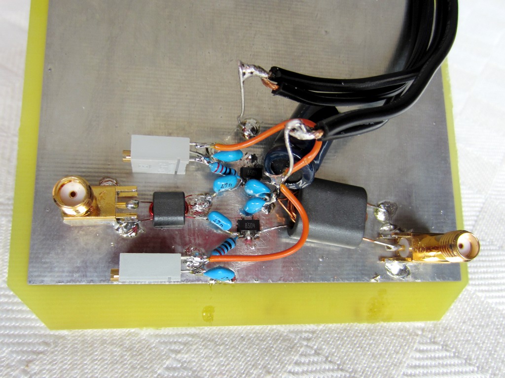
Тобто коли він прибрав середню точку у вхідному трансформаторі вихідного каскаду виконаного по наступній схемі підсилювач став працювати нестабільно та збуджуватися.Input transformer without center tap and gate swamping resistor
Schematic is the same as the previous variant, only the input transformer center tap has been left unconnected.
Unfortunatly I do not have much data on this version, since it proved to be somewhat unstable. With a small signal at the input (< 0 dBm) it appeared to work normally, but as soon as a higher level was applied it started oscillating at around 150 MHz and didn't stop even when the input signal was removed. As said at the beginning, I should probably have added some additional components to reduce the gain at high-frequency, but did not have much time to experiment...